Structures Meet New Making
Seeking to introduce customization into standardized space frame parts, Daniel Thompson (RISD) and I experimented with additive manufacturing for spatial structures. Focusing on customization, we prototyped a series of joint forms for variable strut cross sections, We prototyped with bamboo and 3D printed PLA. In our presentation to industry representatives, we introduced a new work flow for space frame projects that decreases waste, empowers the architect, and enables location flexibility for the manufacturer.
The images included below illustrate chronologically the research project process and results, and the text has come from an article we worked on for publication.

Presentation to industry representatives.
Research Motivation:
With the rise of CAD in architectural design since the late 1980s, our study of and search for form has grown to include what was previously unimaginable; structures that undulate and turn in on themselves, forms derived scientifically from rules of nature or designer. We are no longer bound to what we can compute in our heads and draw on paper. We can design three-dimentionally in the computer with ease.
Manufacturing technology has yet to catch up to the level of effortlessness designers find in CAD design. To create our architectural visions of the future, our go-to structural starting point is the space frame- a three dimensional truss aggregated into a grid that functions as a shell. Through modifying the dimensions of the struts in the space frame, the architect receives a surface that undulates. The current method for fabricating space frames requires custom milling of both joints (“balls”), struts (“tubes”) and their mediator (“cones”). This process is expensive, material inefficient, and provides virtually no variations of material or joint form. Yet, this approach of effectively pre-mades is how designers meet performance requirements.
Can additive manufacturing (processes like 3D printing) give the designer more control of the techtonic expression of CAD designed architecture?
Approach:
This question can be approached through making a space frame with irregular cross-sectioned struts and 3D printed joints. Irregular cross sections must be included because its not cost effective or time effective to mill unique parts, a downside of current spaceframe manufacturing. Yet, hyper-customization is a benefit of 3D printing.
Bamboo has irregualar cross sections, so it is a natural choice for prototype material.
The work began with experiments in small curved reed models and a curiosity as to how the form and structural ideas model small could translate to a built architectural scale. 3D printing enabled us to conceive of a precise full scale model by printing custom joints for members that required no stand in. Our first full scale tests with this process were with 1”x.5” wooden trim pulled into tension with rope tied to PLA t-joints.

Models testing possibilities of form with bamboo and simple joint structures.

The first joint design, prioritizing strength and ease of assembly.
We found an advertisement on Craigslist listing free clippings of a bamboo grove that needed thinning. We visited the site of our materials and hand picked the stalks that would work for our ideas best. After learning much about bamboo, we hauled home the clippings with an average length of twenty-five feet with an average base diameter of 1.5”. As the bamboo decreases in diameter as it grows away from the ground, we discovered that it bends to half heart shaped curvatures, rather than the semicircular forms of the reed. We developed a sensitivity to the material through putting it under stress until fracture as well as tensioning many stalks into bows. When the bamboo is going to break, it sweats out its starch. Rupture occurred at all different places around the circumference on the bamboo- sometimes the tension side, sometimes the compression side and sometimes along the minor axis. Rupture would also occur over time, as many of the pieces in tension broke within the following week. The stalks bent to a parabolic shape were not overstressed and remained intact (Appendix B).
Discovering the achievable curvature altered the arrangement and increased the quantity of members in the proposed form. The iterative nature of this hybrid digital-tactile design process to an axially stressed bamboo structure distracted us from the goal of testing a design build methodology. We see axially stressed bamboo structures as a possible application for our joint technology, as it inspired it, but for proof of concept we simplified to a generic space frame of one bay with three rows.

Sourcing bamboo and testing its material limitations.
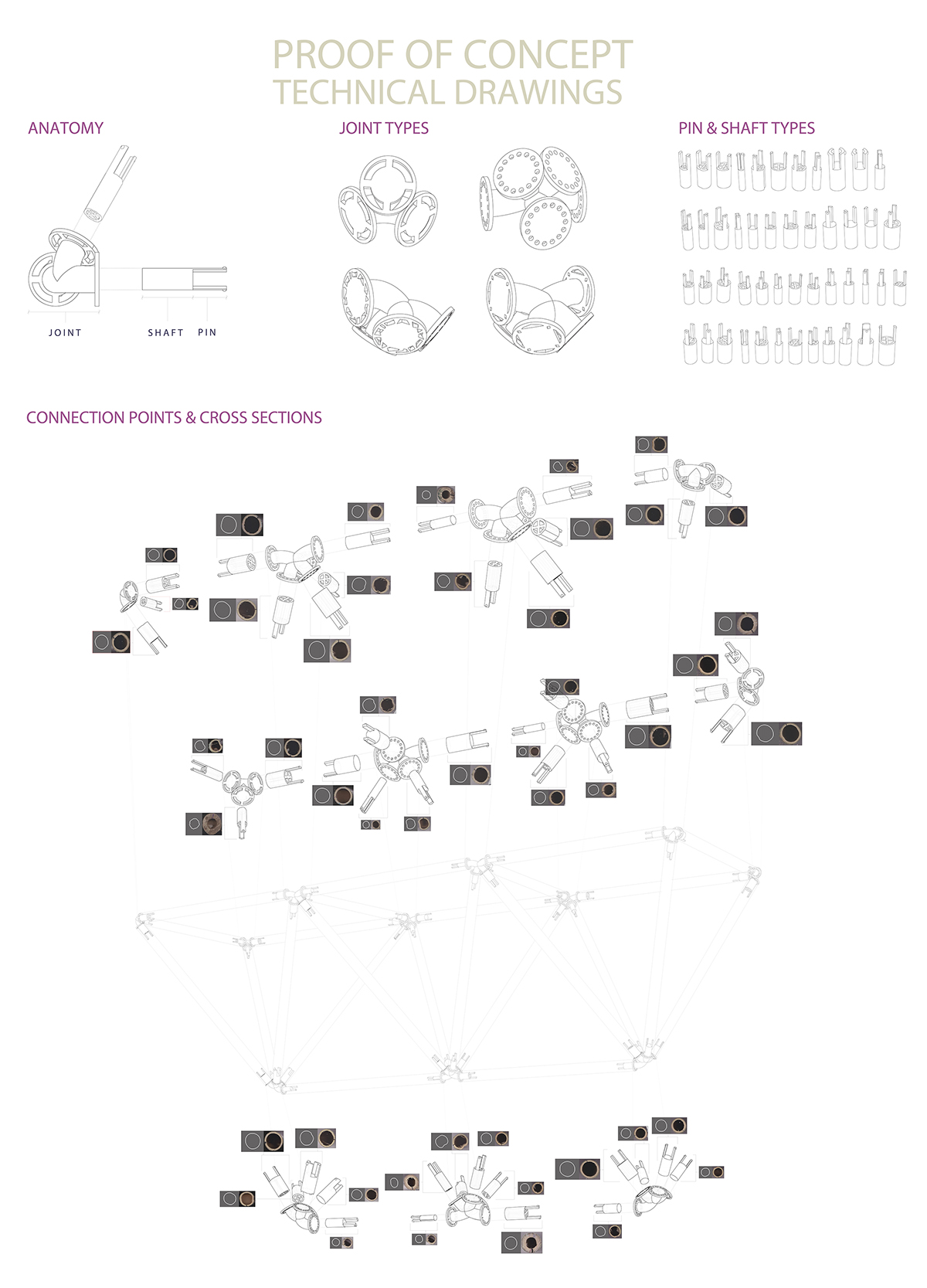
We tested a variety of photographic based data collection methods. We choose portable and accessible scanning technology because of the scale of our members. The table below lists tested scanning methods. The scans were organized into a cross section library in Rhino (see directly above). The library included each image, a spline tracing of the relevant cross sectional information (inner or outer wall), joint names and butt names, and a scaled version of the traced cross section for our model tolerances. We exported packages that contained all the sectional information on a joint by joint basis to make it easy to merge the cross section data with the vector design file.
Making Joints:

Evaluating photographic cross section data collection methods.
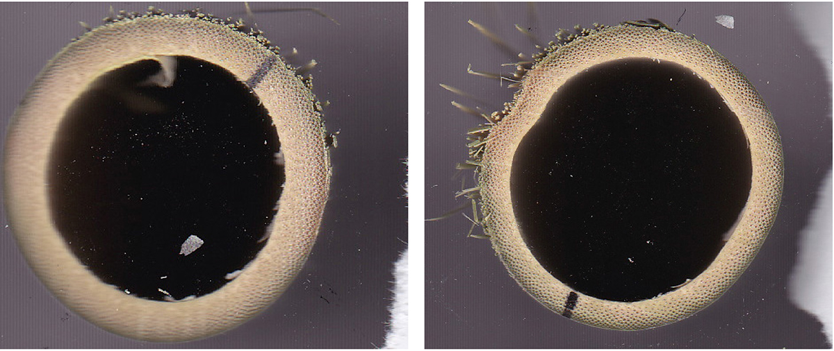
A home scanner provided the most accurate digitization of cross sections.
Joint Iterations:
Joint Design 2: Sleeve. Encase the end of the bamboo.

Joint Design 3: Plug. Fill the interior void of the bamboo.
Successful Joint Type:

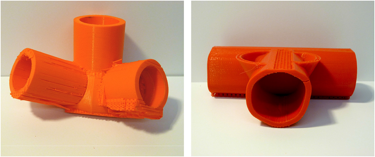
Joint Design 4: Shaft with Expansion Pin. Partially fill interior and ensure a secure connection.
To keep the bamboo on the joint with more than just friction, add an oversized pin to the end of shaft. The pin must be bent inwards when inserted into the bamboo. The desire of the material to return to its natural unbent shape pushes the pin into the bamboo walls to counteract pullout.

Specification for a single joint with five custom cross section structs.
We primarily used a MakerBot Replicator 2 for joint manufacturing. This machine is primarily used by “makers” who create “things,” and is not intended for structural architectural elements. We tested structural capacity of the PLA by starting with a minimum element diameter of 0.5” with default 10% infill. After quickly breaking this piece, infill increased to 55% with joint connection diameters of 0.8”. This had an appropriate ratio of print time to strength.

We constructed the space frame upside down for stability, starting with the top chords and braces. This orientation was enabled by the model’s small scale. After laying the top chords and braces in their proper positions, the corresponding joints were inserted into the bamboo starting with the corner joints followed by the middle joints. We referenced a simple diagram to ensure correct positioning. Next the pyramids were connected to their apex joint and slid into the upper chord joints. After all three pyramids were assembled, the bottom chord struts were fitted.
We succeeded in not needing any tools for assembly and two builders were sufficient. It would have been possible for only one builder had the joints been of a less brittle material. The unique sectional properties of the bamboo as well as the axis mark made it easy to tell which side needed to face up to slide onto the shaft. Rotation errors from the design phase that came to light during assembly were mitigated by the shaft tolerance. The partial frame flexed enough to allow every piece to slide into place, however we suspect that our material choices enabled this as it is not a universal space frame trait. The resulting frame is impressively rigid albeit delicate. The PLA was quick to fail along layer seams when under load, caused by the orientation of the joint in the Makerbot and also the strength of the PLA when printed as a surface. Although the PLA fractured before pull out, additional security could’ve been added by simply making the spheres at the end of the pins a bit larger. Because each bamboo piece is irregular, the top chords are deflect off plane by 0.5” over the 12’ span. Negligible sag was caused by flexibility of the PLA.


From our prototyping, we created a manufacturing process for space frames using additive manufacturing:
The left of the below image is the current process, known as ball and tube, and the right is the proposed process with additive manufacturing.


